NDT test results for detecting air voids in chicken eggs
 As you realize, there are a great variety of cases and materials and we cannot check all of them or have some readily available information about them.
We stopped accepting customer’s samples for checking feasibility of applications a few years ago. Each material has its own transmission ratio, thickness, internal structure/configuration and many other aspects). The devil is in the details, as we say. So, irrespective of how promising and feasible some of the applications our customers are interested in and inquire may look at the first glance, we cannot guarantee successful use upfront without testing.
Once in a while our R&D team may select one interesting application and arrange testing of its own, especially if target material (samples) are locally available of can be easily obtained.
This was the case with checking air voids in eggs. Having received a few similar inquiries aimed at NDT of chicken eggs, we decided to test the capabilities of our THz imaging cameras/systems in transmission mode for this application.
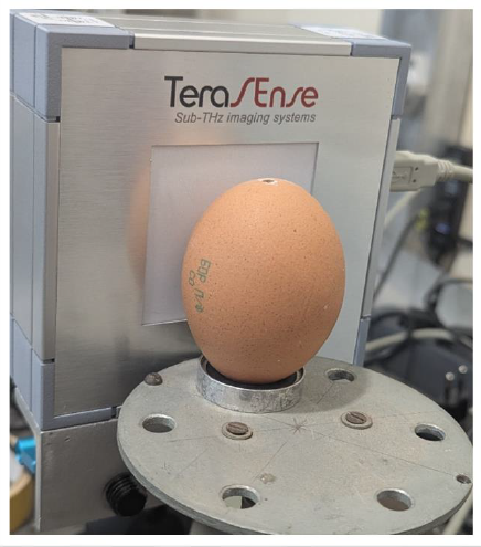
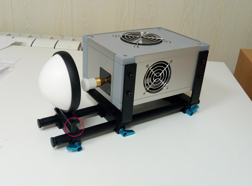 The setup consisted off our standard 2D/matrix THz imaging camera Tera-1024 and our basic 100GHz (80mW) wave source (IMATT generator) with our conical horn antenna and a collimator lens. The egg was placed near the camera sensor array surface and was positioned vertically as in the image below.
The air voids in eggs were produced by drilling the egg and subsequently pumping out a certain amount of the egg contents using a syringe. The exposition parameter for the camera was set to 5 to achieve the optimal image.
TEST RESUTLS
You can see here THz images of two different eggs. Full & pristine egg is on the left-hand side, while the right-hand image shows the egg with 30 ml of content removed.
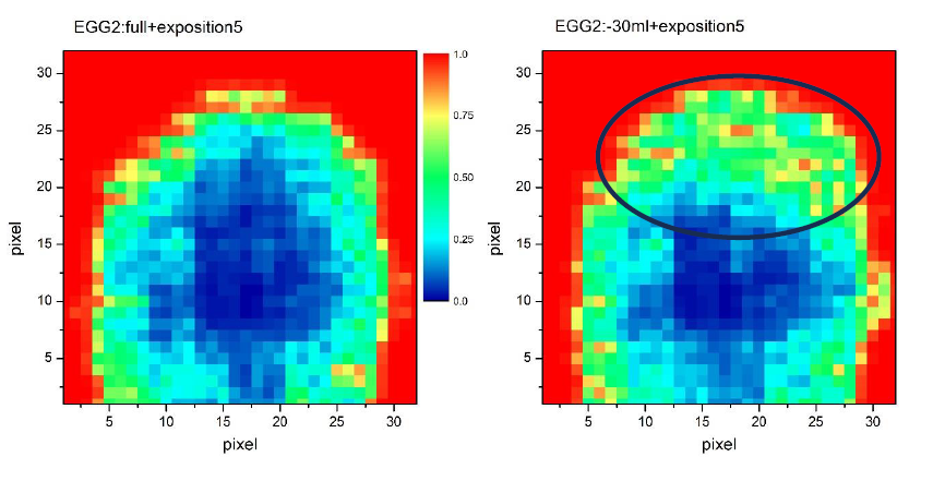 | ||
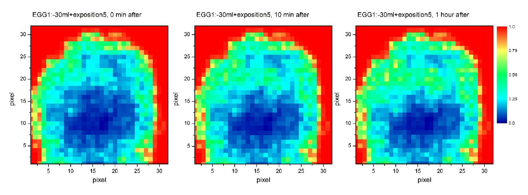
| Note that after removal of egg content, the image evolves with time, as the egg liquid slowly dries on the inner walls of the egg. | ||
 | ||
The main challenge that we faced was the shape of the egg, which is not flat and this complicated the task. It’s remarkable, but the output power of 80mW of our basic 100GHz waves was revealed to be ideal, as using a more powerful wave source could have resulted in overexposure. Of course, this picture (THz images) may look a bit blurred to an unsophisticated eye who would prefer a higher imaging resolution. Yet, we believe the test objective was met. Besides, another peculiarity of this test is that it makes absolutely no sense in using our 300GHz scanner with higher imaging resolution capability, because the level of diffraction at frequency of 300GHz is much higher than at 100GHz and would completely kill the whole THz picture.
Even though it’s hard for us to judge whether it can match expectations or our customers, who pursue similar applications, but the difference in 30ml is pretty tangible in THz images and can definitely be detected. Our expert responsible for conducting this test used our THz matrix THz imaging camera with pixel pitch 1.5mm (same as with our high speed linear THz imaging scanner system at 100GHz which fits better industrial inline NDT applications).
If you have any questions with regard to this test or any other applications, feel free to contact Terasense.