IMPATT diodes

  • icon

    High power

  • icon

    Power stability

  • icon

    Fixed frequency

  • icon

    Compact

  • icon

    Low cost

  • icon

    Long life

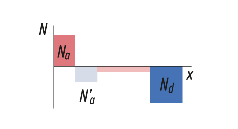
The Impact ionization Avalanche Transit Time (IMPATT) diode is a type of high-power semiconductor diode utilized in microwave applications at high frequencies, from several GHz to several hundred GHz. Having negative resistance, IMPATT diodes are naturally used as oscillators in high-frequency signal generation. However, one of the key advantages of IMPATT diodes over the other microwave diodes is their relatively high power capability. On a historical note, IMPATT diode is also called ‘Read’ diode in honor of W.Т. Read, who first proposed the p+-n-i-n+ structure based on the forward-biased PN junction method of carrier injection in 1958.

IMPATT diode operating principles

Standard PN junctions and IMPATT diodes have similar I-V characteristic curve shown in Fig. 1a. As indicated in the figure, when the forward bias voltage reaches the “turn on” level, the diode starts to conduct in the forward direction while preventing the reverse current. As soon as the bias voltage applied in reverse exceeds the breakdown point, the diode starts conducting in reverse direction due to the avalanche breakdown phenomenon.

For the purpose of microwave signal generation, there are different types of IMPATT diode structures that can be used. Figures 1b-1e illustrate its basic operating principle considering a p+-n-i-n+ semiconductor structure as an example.

In this case, there can be identified two distinct spatially separated regions shown in Fig.1b, the avalanche multiplication region (the forward-biased ‘p+-n’ junction) and the carrier drift region (the i-region which becomes completely depleted at high reverse voltages). This particular arrangement creates the carrier distribution profile indicated in Fig. 1c and Fig. 1d.

The former region is where the injection of carriers (the rapid increase in the number of free charges) occurs. Due to maximally high electric field intensity across the junction (Fig. 1e), the newly formed holes are accelerated into the heavily doped p+-region resulting in impact ionization which, in turn, leads to avalanche carrier multiplication.

The electrons, on the other hand, are forced through the latter region, where they drift in a constant electric filed (Fig. 1e) and then into the n+-region. Provided that the electric field strength in the lightly doped n-region is high, the electron drift velocity remains almost constant. Therefore, with the differential electron mobility being close to zero, the volume charge density does not decrease with electron flow.

When the reverse-bias voltage is increased to the point where the electric field in the p+-n junction exceeds the breakdown level, the impact ionization coefficient α reaches high values. Hence, the depth of the impact ionization region is kept small because of strong dependence of α on the electric field intensity level.


IMPATT diode I-V characteristic
Fig.1a
How does an IMPATT diode work: carrier drift within an IMPATT diode
Fig.1b
How does an IMPATT diode work: carrier drift within an IMPATT diode
Fig.1c
Fig.1d
Fig.1d
Fig.1e
Fig.1e

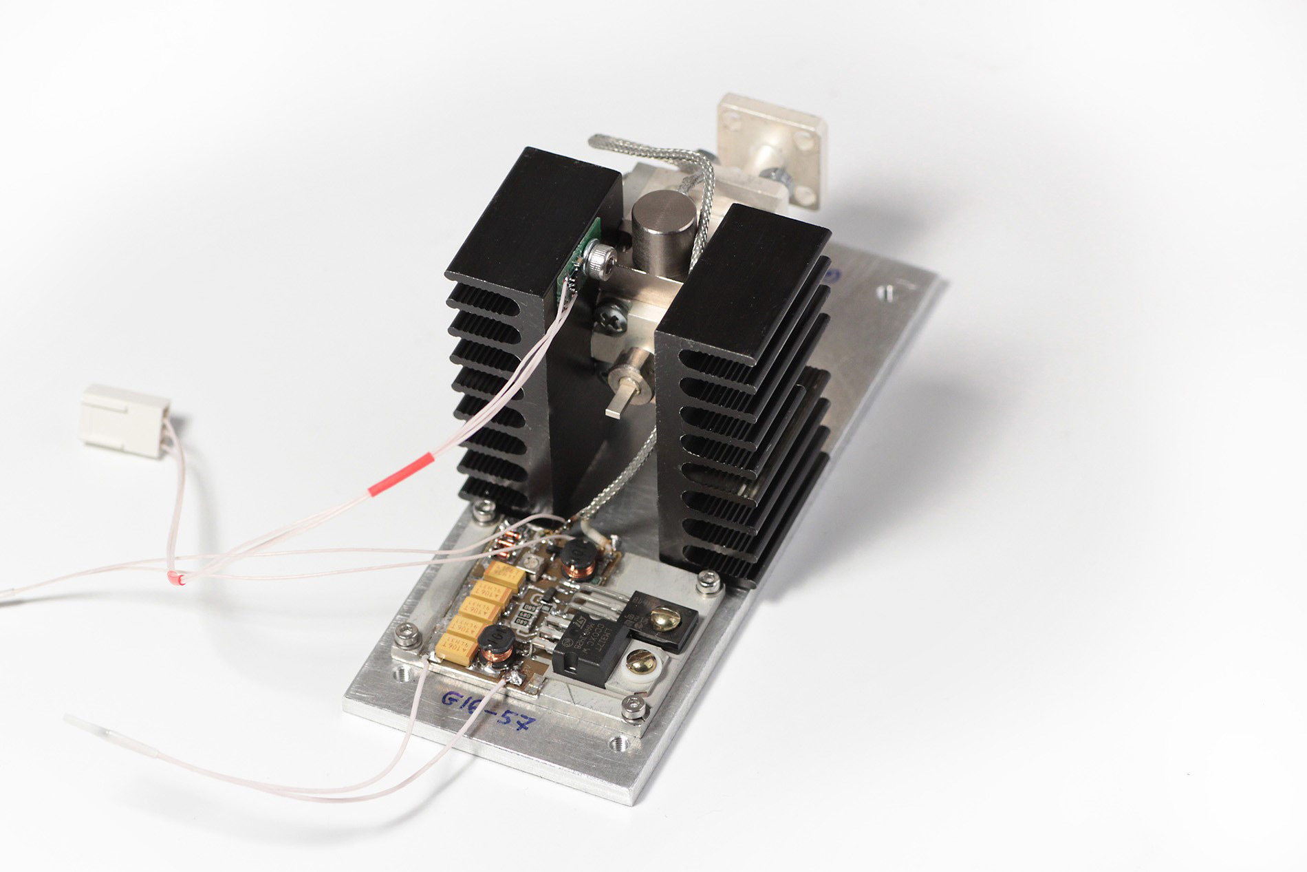
IMPATT generator circuit

Fig. 2 shows a general circuit configuration for the IMPATT generator. To ensure stable and reliable operation, the diode is driven by a supply source through a current-limiting resistor and an RF choke to provide DC isolation from the radio-frequency signal. In order to sustain oscillations at a specified frequency, the IMPATT diode is typically integrated into a tuned resonator circuit, such as a waveguide cavity.

Compared to the other kinds of microwave negative-resistance diodes, with the IMPATT based generators it is possible to achieve much higher output power levels. IMPATT generators have also proved to be some of the most efficient and cost-effective high frequency and high power sources with remarkably long life of stable and reliable operation.

Typical IMPATT diode oscillator circuit

img
img
img

Have any questions?
Please contact us.